32 channel DMX controlled LED (or motor, or ...) dimmer / switcher
News
flash: an improved design is now available for purchase!
Go here.
This web page documents a DMX-controlled lighting board for LEDs (or
anything DC powered).
Board size: 6.25 x 3.75 two-layer
Project timeframe: July 2005
Client: Leo Villareal
Initial webpage creation: August 16 2005
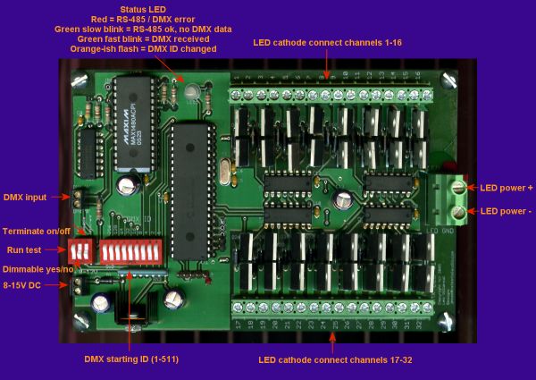
Top view:
Larger Image
Feature set:
- Fully isolated RS-485 input (MAX1480)
- Each channel can switch 10A, total current capability 30A
continuous
- Diode protection from inductive load switching spikes
- 250 levels of dimming, PWM "slice time" is 60usec (67 Hz cycle
rate), no flicker at lowest brightness
- DMX ID settable 1-511 via DIP switch, changes are immediate (no
power-cycle needed), status LED blinks orange to show change detected
- RS-485 termination on/off via DIP switch
- Dimmable yes/no via DIP switch (to protect non-dimmable equipment
from damage)
- Run a test chase pattern yes/no via DIP switch
- Status LED indicates RS-485 / DMX error (red), good but no data
(green slow blink), and DMX frames incoming (green fast blink)
- 8-15V DC @ 150mA, reverse polarity protected
Significant parts:
Maxim MAX1480ACPI, fully-isolated RS-485 transceiver
Microchip PIC18F442
RFP3055LE TO-220 11A 60V NFETs
74AHC595 8-bit shift register with storage register
Phoenix Contact 1714971 2-position 30A terminal block
Phoenix Contact 1935307 16-position 16A terminal block
All parts except for the Maxim IC are available at digikey.
Background
My client has large LED displays and wanted a means to control them via
computer or other devices in a standardized way. The design is
such that more boards can be easily built as needed. One of the
several installations this board was used to run: Disorient
2005/2006
Technical discussion
Please see the writeup for the similar AC dimmer board for discussions of
RS-485, DMX, and board design. This design is intentionally as
similar to that one as possible.
The PWM for this design is done in software (of course, no
microcontroller has 32 hardware PWM channels), using some flexible code
that was written for a prior design. The main routine is called
from a periodic interrupt, all the code (in C) is carefully coded and
unrolled with macros, compiler output checked to ensure nothing stupid
was happening, and time in the routine and call rate was monitored with
an oscilloscope. So each call of the routine advances the PWM
count for each channel, the on/off bit pattern (4 bytes) is created,
the four bytes are sent to the shift registers via SPI @ 10Mhz, and
then their outputs are updated simultaneously, turning the NFETs
on/off. Doing this achieved 32 channels of 250 levels with about
40% CPU utilization, leaving plenty of time for the few other tasks the
design needed.
Mistakes, tools and future work
All in all pretty good, pcb changes for the prototypes were minor and
are easily fixed for the next run of boards. The two errors that
were made:
- FET protection diodes were tied to +5V, which is just
wrong. They have to be tied to the + of the LED (or whatever)
power supply. Using a dremel with cutting wheel easily cut the
necessary traces and the patching was pretty straightforward.
- The test mode yes/no DIP switch wasn't routed to a PIC pin.
Ooops. But there were unused PIC pins (going to holes on the
board for future tweaking) so this fix was trivial.
Tools used: Eagle 4.15 (latest of this writing), which
I wholeheartedly recommend, and the CCS PCH C compiler, which was
horrendously buggy for 18 months and is now more or less reasonable.
Schematics? Board layouts?
Gerbers? BOM? Software downloads? ...
Sorry, this was a paying client project and the IP is not available for
give-away...
However! an improved design is now available for purchase! Go here.
Home