16 channel DMX controlled 3500W AC light switcher
This web page documents a DMX-controlled lighting board.
Board is 6.25 x 3.75 two-layer
Project timeframe: July 2005
Client: Leo Villareal
Initial webpage creation: July 8 2005
Minor edits July 15 2005
Top view:
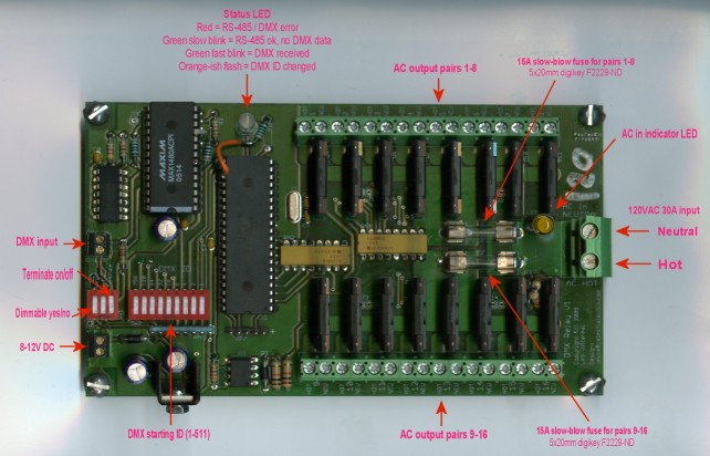
Larger Image
Feature set:
- Fully isolated RS-485 input (MAX1480)
- DMX ID settable 1-511 via DIP switch, changes are immediate (no
power-cycle needed), status LED blinks orange to show change detected
- RS-485 termination on/off via DIP switch
- AC dimmable yes/no via DIP switch (to protect non-dimmable lights
or other equipment from damage)
- Dimming synchronized to AC zero-crossing
- AC triacs isolated
- 240W per channel as built for cost savings, up to 1000W/channel
possible. No snubber circuitry for cost savings, but snubbers for
each channel possible
- Single 30A AC input
- Dual 15A fuse protection
- AC power-is-on indicator/warning LED
- Status LED indicates RS-485 / DMX error (red), good but no data
(green slow blink), and DMX frames incoming (green fast blink)
- 8-12V DC @ 300mA, reverse polarity protected
Significant parts:
Maxim MAX1480ACPI, fully-isolated RS-485 transceiver
Microchip PIC18F442
6N138 optoisolator (for AC zero-cross detect)
Sharp S102T01 solid-state relay, 2A rating (higher ratings available)
Phoenix Contact 1714971 2-position 30A terminal block
Phoenix Contact 1935307 16-position 16A terminal block
All parts except for the Maxim IC are available at digikey.
Background
My client has an 80-channel board from years ago that plays fixed
patterns (no DMX or any other inputs) for an art piece that has now
been sold. In order to make the piece more modular and flexible
in terms of control options and installation (the 80-channel board is
one huge pcb), I was tasked
with designing something with the same solid-state relays (they have
worked great) and new everything else. In addition, the ability
to control high-power lighting - several high power lights as well as
16 lower-power ones that add up to a lot - was desired.
Technical discussion
AC power design was something new for me, and it was exciting to figure
out the practical aspects of designing for it. To start off with,
you have to get power in! There are limits to what terminal
blocks of reasonable size can handle, and I spent awhile digging
around. The 30A one I used is sensibly sized and is around the
limit of what is normally available as AC feeds. While higher
current blocks are available, they are much larger and are overkill for
the situations this board is designed for.
Fuses. Fuse the AC hot side, not the neutral, so if the fuse
blows, the hot is disconnected. Of course, without a polarized or
3-prong plug there is no way to ensure the AC is wired correctly.
As it turns out, 30A fuses are relatively scarce, so this design splits
the 16 outputs into two banks of 8 with individual 15A fuses.
This is better for a number of reasons: pcb traces can be reasonably
sized, connections to normal 15A or 20A circuits are protected (vs.
with a single 30A fuse), and current limits on the 8-pair terminal
blocks are respected.
pcb trace width - turns out you need a fairly wide trace to keep the
board from getting toasty. This was a useful tool for me:
Trace
Width Calculator
and I used 2oz copper, which pcbfabexpress.com (my favorite prototype
place) uses for their boards.
RS-485 isolation. Isolation is desirable in situations where you
can't control how an installation is wired. If having a common
ground between all RS-485 devices is possible and there aren't power
lines running parallel to the signal pair, it probably won't be
necessary. In this case these boards will be used in situations
where the RS-485 comes from something powered by one generator and the
AC for the lighting from another, installed and run by people who don't
do it for a living (and very well may not be sober at the time!) the
more robust, the better. The Maxim IC is pricey at $16 each (vs.
$1 for a standard RS-485 transceiver) but it does it all.
Zero-cross detection. To do good dimming, it has to be
synchronized with the zero-crossing of the AC line, since once turned
on, triacs stay on until the AC voltage goes to zero. So the
strategy is to time when you turn them on (briefly) such that you get a
fraction of the remaining AC cycle, and you know how much of the cycle
they are on for. Important disclaimer: dimming has not been implemented in
software yet in this design, so there may be subtleties to this
that have not been reached. The hardware detection works
great, and is based on the elegant zero-cross design in the circuit
below (lower left corner, the 6N138). Important: R22 & R23,
the 10K resistors on the AC line, must be 1/2W. MIDI dimmer
w/zero-cross (pdf schematic)
DMX receive software. The DMX specification is on numerous
websites (like here)
so I won't discuss it. Generating DMX is cake, but receiving DMX
with a
microcontroller can be a little tricky. One simple way is to send
the signal to both the UART and another pin to trigger an interrupt,
and use timers to count how long the signal has been high or low or
whatever so the detection of the DMX break and mark-after-break doesn't
involve the UART. Unfortunately in this design there were
absolutely no extra pins on this PIC, so it had to be done with the
UART alone. I found some code on the user forum for CCS, the
used-to-be horrendous but finally relatively bug-free C compiler I
unfortunately use. (CCS
forums) There is no way to link to the post, but searching
for DMX will yield some results. I completely rewrote it for my
needs but followed his strategy and it works fine. In essence
framing errors are used to determine DMX start of frame, and a framing
error with received data of zero indicates the frame started, and if
the next byte is received without error and is a zero it is the start
code.
The entire design is through hole, another request from my client, so
that it can be soldered together by "normal humans" and not require
machinery or me with the fine-tip soldering iron and magnifying
glass. As it turned out, most of the design had to be through
hole anyway - terminal blocks, fuses, solid-state relays, Maxim chip-
so
this didn't add much to the board real estate, and simplifies contract
assembly as well, it can just be run through the solder wave.
However,
this precluded using a higher pin count PIC, which would have
simplified DMX receive software (see previous paragraph)
and opened the door to more DIP switch options.
Mistakes, tools and future work
All in all pretty good, pcb changes for the prototypes were minor and
are easily fixed for the next run of boards. The two errors that
were made:
- polarity of the driver enable pin on the MAX1480 was wrong.
DE (called DE' as well) is active-high or active-low depending on if
the datasheet is talking about the pin itself (page 10) or the resistor
driving it (page 12). Confusing. Page 16 has a truth table
that spells it out - the resistor R2 (page 12) is needed even if it
will never be used as a transmitter and is tied to ground to disable
the transmitter.
- I assumed it would be possible to configure the PIC so that the
UART transmit pin could be used as a general-purpose i/o while the
receive pin goes to the UART - nope. If the UART is enabled, both
pins are for the UART. Kinda dumb and an unfortunate restriction
- other microcontrollers don't require this, and it wastes a (valuable
in this design) pin. So I had to do board patch and deal with
receiving DMX with just the UART - see above.
Future work - dimming is not implemented! As soon as my client
needs dimming capability it will be added. In order to work
outside of the US, it will support both 50hz and 60hz,
auto-detect. Operation at 240VAC would be great, however the
Sharp solid-state
relays are only rated for 125V (not sure if a 240V version is
available) and the resistors that current-limit the zero-cross
optoisolator and the AC-is-on LED have to be 20K, not 10K. Not
sure if the terminal blocks are rated for 240VAC either.
Tools used: Eagle 4.14 (latest of this writing), which
I wholeheartedly recommend, and the CCS PCH C compiler, which was
horrendously buggy for 18 months and is now more or less reasonable.
Schematics? Board layouts?
Gerbers? BOM? Software downloads? ...
Sorry, this was a paying client project and the IP is not available for
give-away. If you would like to purchase some boards or have a
proposal for commercialization of the design, feel free to contact me.
Home