Louis Vuitton's newest store, the biggest in North America,
opened
today (Dec 3 2009) in Las Vegas, at the Crystals in
CityCenter.
I'm delighted to say I designed all the electronics that run the
LEDs!
The stainless steel façade contains 4000 1-watt white
LEDs
with a nice color temperature (not too yellow, not too cold white)
and
a
novel 360 degree light throw, making them easily visible from all
directions. Electronics to run installations of this scale
aren't
available off-the-shelf, and besides the obvious requirement of
smooth,
flicker-free dimming the project required:
UL approved everything (of course)
Easily swappable electronics, so any failures can be
quickly
fixed
Continuous monitoring of power supplies, temperature, DMX
signal, etc.
A test mode to detect broken LEDs and/or wiring
Remote (web-based) monitoring and restart of every board
that runs LEDs
Works with standard DMX lighting protocol, so the
animations
and
sequencing can be done with high-end lighting control systems
I'm happy to say my hardware design achieves all this.
The installation comprises of 80 separate 60-channel LED driver
boards,
each with its own power supply, mounted on an aluminum "shelf" and
installed 10 per cabinet, 8 cabinets total. The driver
boards
watch for power supply problems and over temperature and LED
failures
continually while they run, and
each cabinet has one Ethernet-enabled monitor board that queries
each
of the 10 driver boards and reports all information via a
generated
webpage. So a technician can look at one webpage to see the
status of everything in a cabinet at a glance. Additionally,
each
driver board and the monitor board has a LCD display showing
status,
updated continually.
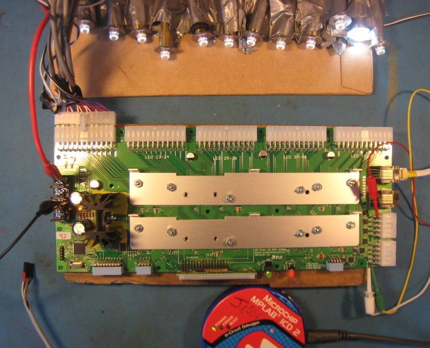
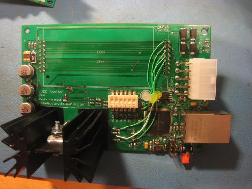
Top view:
The LEDs are plugged into the back connectors, 12 per connector, 5
connectors total, for 60 LEDs total. This allows the board
to be
removed from the LEDs it drives reasonably easily. Each
connector
has a 5amp fast-blow fuse for UL safety requirements. The
two
metal slats on the board are heatsinks, under them are 15 driver
chips. On the left is +5V power (two connects for +5V and
two for
ground, since it is 20amps peak) and on the right is DMX input (on
cat5
ethernet) and another connector for +12V board electronics power
and
RS-485 based monitoring.
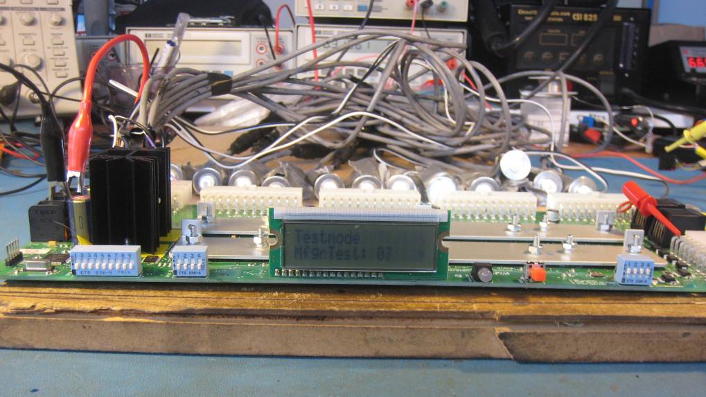
Front view:
This shows the little LCD status display, DIPswitches to select
DMX ID
and UnitID (i.e. which# of the 10 this board is in its cabinet),
several test modes and termination on/off, a bicolor DMX signal
status
LED, and an orange reset button.
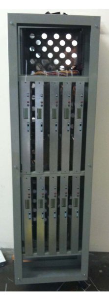
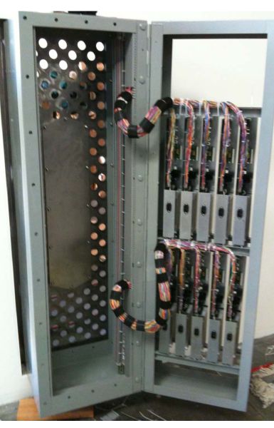
Here's two photos of them in a cabinet, being assembled, the
left
picture is the front view and the right picture the
"back". They
are mounted vertically on a "door" that can be opened to get
to those 5
big connectors for removal if necessary. There are 8 of
these
cabinets. I wasn't involved in any of the actual
assembly and
installation, fortunately, just consulting by phone as
needed.
There is a lot of wire out there.
As with most projects, this one is a combination of reworked
existing,
proven designs and new stuff. And as with most projects
it wasn't
without some stress-inducing gotchas, both due to mistakes I
made and
showstoppers I had no control over: bugs in the C compiler
(CCS for
PIC18F series) and in the
driver
chips themselves (TI TLC5940). However, I try
to do
designs with a "plan B" in ways large and small when
possible/practical, and I hateto
fail, so after some effort all issues were resolved or worked
around
satisfactorily, and now LV Las Vegas is the newest neato
lightshow on
the Strip!
A hearty "thank you" to Meritronics
for the manufacturing of 90 of these driver boards on pretty
short
notice and working around some minor board layout snafus.
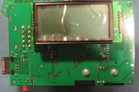
Ethernet monitor board front view:
Back view:
These are a lot less exciting looking than the driver
boards but
are
vital for the long-term health of the installation.
These are
installed in each cabinet, and wired to each of the 10
driver boards in it, and continually display a summary of
driver
boards' status on the LCD (photo doesn't show text, sorry),
have a
red/green status LED (showing "good/problem" at a glance) and
most
importantly via
a webpage the board creates on demand with up-to-the-second
status of
everything. This uses the Freescale MC9S12NE64
16-bit
microcontroller
with built-in Etherenet MAC & PHY, so with
appropriate firmware it is a one-chip custom webserver. I
took this
project,
designed
a
new board, cut a bunch of code, added some new stuff, fixed
a few minor mistakes and voila - remote monitoring (and click a
link to
reboot!) of all of the boards that run all the LEDs.
Thanks for reading!
I design stuff like this all the time, if you have a project you
need
custom work for, drop me a line.
Also see DMX LED drivers for sale.