Terp: wirelessly sequenced mp3 player
This web page documents a design of two boards: a wireless transmitter
and receiver for mp3 playback for choreography.
Board size:
Project timeframe: late 2002 - mid 2004
Client: Patrice Regnier
Webpage created: May 25 2007
News
flash: Patent granted late 2010!
The Terp project
was to create a way to sequence commands sent to headphones worn by a
group (dozens) of people. Key requirements were to be able to
send the same command to more than one person (i.e. to a sub-group) and
to have different commands be recieved by different groups
simultaneously. After some design investigation it was clear that
no analog FM type system was going to cut it, WiFi would impose serious
cost and power requirements on the receiver units, bluetooth wasn't
very cheap and range was nowhere near good enough.
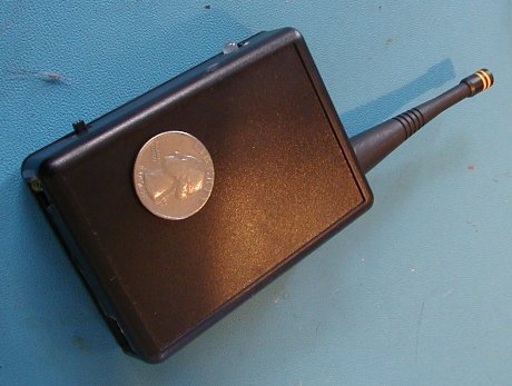
First, the gear photos. For each terp installation, there is one
transmitter (connected to the sequencing computer or MIDI keyboard),
and each participant wears a receiver.
The receiver, in a box as worn (velcro straps not shown):
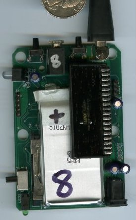
The receiver board, top view:
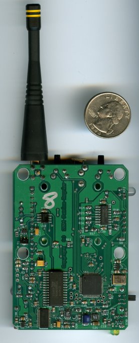
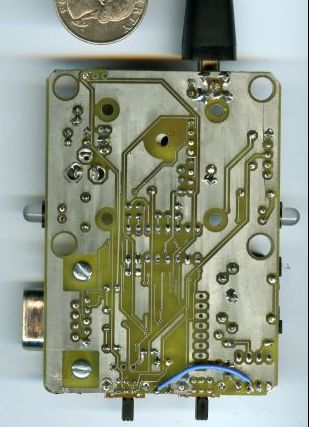
Receiver board, bottom view, where all the juicy EE action is:
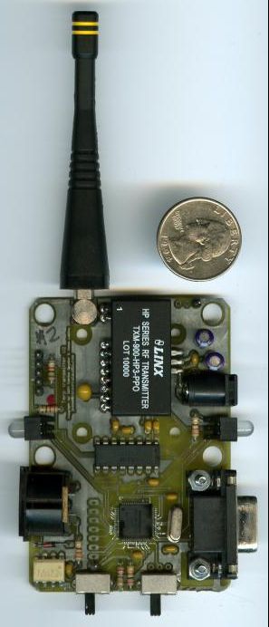
Transmitter circuit board, top:
Finally, transmitter bottomside:
Terp overview
The terp system is designed to have dozens (for now) performers to
recieve prerecorded spoken-word instructions at specific times, as
sequenced on a custom Mac application or by playing a MIDI
keyboard. By organizing people into groups of different sizes and
choosing different commands at different times a variety of
interactions can be choreographed with no rehersals.
Each performer wears a terp receiver on his/her arm (held with velcro
strap) and headphones. The performers are just ordinary people,
no special abilities required. Commands might be "shake hands
with your neighbor", "sit in the chair" (received by a single person),
"walk in a circle around the chair" (everyone else). See here for action
photos and a link to a video clip.
Design
After briefly examining other wireless systems, it was clear
that sending the audio itself over the air was not feasible, and for
long range (like 1000') a 900Mhz band system would be needed. In
order to save significant per-unit and development costs, the system is
one way: a transmitter sending to all receivers, only. This has
the drawback that the transmitter cannot know that a receiver did in
fact recieve the message.
The system works like this: the one transmitter is plugged into the Mac
via RS-232 or a midi keyboard, each reciever has a removeable
Smartmedia card (socket is under
the silver li-ion battery in photo of top of receiver unit above) which
holds a pile of mp3 files (each of which is a spoken command) and a
configuration file, which tells the receiver it is plugged into what
unit # it is. When the transmitter receives a "play this file"
message from the Mac, or a key is hit on a MIDI keyboard, it forms a
"command packet" that includes the file to play, group number, and and
in incrementing packet count, and generates a 32-bit CRC of this
data. This command packet is broadcast twice, and the group(s)
that this command is for is noted. When the tranmitter is not
receiving new command from the Mac, it resends each command packet for
each group over and over, so that if the command packet wasn't received
correctly the first time, one of the retries will make it. When
the receiver senses data coming in over RF, it locks onto the command
packet start sync bytes, queues the data, then checks CRC to ensure it
was correctly received. If correctly received, the file is found
on the Smartmedia card, and the mp3 data is sent to the mp3 decoder,
which goes to a combination DAC and headphone amp.
As one might imagine, there are a lot of details to all this. The
receiver is about 6500 lines of C code (all written by me), at least a
third of
which is to manage finding files and walking FAT12 filesystems, with
support for long file names (a nightmare) and subdirectories. The
receiver also has various test modes for range checking and keeps track
of good/bad packets received, and has a number of built-in words to
report status & various error conditions to the user. The
STA013
mp3 player chip, while popular, is poorly documented (shame on
you ST) and I couldn't have
gotten it running without tips from this excellent website.
However, the biggest issue was the atrociously buggy C compiler from CCS.
I
found literally dozens
of bugs, 5-10 of which were major, can't believe-they-sell-it grade,
and cost at least 100 hours of unforseen debugging to identify and
resolve. The biggest one was inability to handle const arrays
larger than about 240 bytes. The 4K of const data required to
load into the STA013 (essentially to configure the DSP in it) was being
mangled, and since the Smartmedia-to-headphones chain was being brought
up for the first time, it took approximately 35 hours of hair-pulling to work
things out enough
to prove it was yet another CCS bug. Now, this was 3 years ago,
and after more than 150 bugfix
releases
of the compiler, often including fixing regressive bugs
(proving their test suite is nonexistent), it stabilized to the point
where it
can be trusted for at least things that are typical C code. The
problems with this compiler meant my earnings on this project were less
than $5 an hour and nearly ended my career. Since then, they seem
to be under new management and have significantly improved quality and
tech support.
A tour of the receiver
The photo of the receiver top shows the following:
- top of board: volume up, volume down buttons, 3.5" stereo jack
for headphones, and antenna for RF module
- bottom of board: 2-up LEDs to show battery charging / battery
low, DC input for recharging battery, and Smartmedia socket, hidden
under the silver colored battery.
- left side of board: single red/green LED that flashes various
ways to show packets being received (or errors), if it is in normal or
test mode, etc. Also the on/off switch.
- stackup: the black thing is a Linx
HPIII receiver in the through-hole package, which is bend over
90deg and plugged into a row of socket pins, which in turn are plugged
into another row of socket
pins, which are plugged into the board. Just underneath the HPIII
receiver is a 1200mAh li-ion battery (for 8 hours runtime), with
inconvenient "solder tabs"
(the only availabe back then), which are soldered to the board and
epoxied over for safety. Underneath the battery is the Smartmedia
socket. This stackup is the minimum height (aka thickness when
worn) and allows it to be fit in the Hammond model 1593 case.
The board bottom photo is where
all the EE action is. The large LQFP is a PIC18LF6720,
which
runs the show. The smaller TSSOP on the bottom edge on the
left is the TI TLV320DAC23PW, a combination DAC and headphone
amp. To the right of it the SOIC is the STA013 mp3 decoder.
Its hard to see, but on the bottom right is a Linear LTC3440
micropower buck/boost DC/DC converter,
essential for converting the 3V - 4.2V working range of the li-ion
battery into a steady 3.3V. Also on the board (upper right SOIC)
is a TI BQ2050
battery "gas gauge", a Linear LTC1734
li-ion charger controller, and a Linear LTC1440
micropower comparator with built-in voltage reference, which is used to
auto power down everything if the battery voltage drops below about
2.9V. This is essential because if a receiver is accidentally
left on, draining the li-ion below 2.7V or thereabouts
will cause permanent damage. An important part of this design was
to put as much on the bottom as possible, and all SMT (0603 size when
possible), and all low-profile. The bottom of the board sits just
a few millimeters from the bottom of the case. Unavoidable tall
items (like electrolytic caps) were put on the topside.
As of this writing 30-odd of these have been made over the past several
years, all hand-soldered by myself, and all are fully working.
The board above is the final form. The first proto was actually
more of a "custom development board", shown here. Note it was
hand-etched! Crazy. But fun. But crazy for any kind
of paying project. With wire-wrap and some hacks, it was finally working. Being that
this was a very early project in my career, I did another spin of the board to
ensure I had things right before doing the final one. Nowadays
for a project this simple (it wasn't simple to me back then, but was 4
years ago) I'd probably just do the final form first, then do a number of small
fixes, then the production version. The only time I do a
"R&D" prototype anymore is to check pro-audio grade analog
precision designs. Anything digital or non-precision analog I
just go for the production design the first try.
A tour of the transmitter
Compared to the reciever, the transmitter is dirt simple. The
switches select between MIDI input, RS-232 input, or auto-test-mode,
useful for range-checking the receivers in a new performance
space. The LEDs blink to show operation and when new serial
commands or MIDI is being received. The only part of this of any
trickyness is keeping various "state" information about the last packet
sent to different groups, so that it can repeatedly transmit packets
between receiving new serial commands or MIDI messages, and managing
simultanous packet transmission to receivers while receiving new
commands from the Mac. The board fits into the same case as the
receiver, with different slots & holes cut for the different
switches and connectors.
Conclusion
All in all, a pretty nifty thing, and I've always wanted to create a
mp3 player. By far the worst part of the project was dealing with
CCS C compiler bugs. Writing FAT12 filesystem code to read
Smartmedia cards was no picnic either, though in 2002 there were
several issues of Circut Cellar that described the layout which was
very helpful. This "first generation" is limited by having only
one-way RF link (unavoidable given costs and required range at the
time) and using Smartmedia - a format beginning its decline in 2002 and
now dead.
Home