48 channel DMX dimmer pack (Version 2!) for LEDs and most
solid-state relays (SSR)
This
board
is for sale!
Discontinued as of March 2011. See bottom of page for support
information.
Board size: 3.5" x 4.0", with 4 holes for 6-32 screws; a set of 4
1/4" standoffs are provided. There are 3 holes at the corners
and one near the bottom right, at 2.49" x 0.16" relative to lower
left corner.
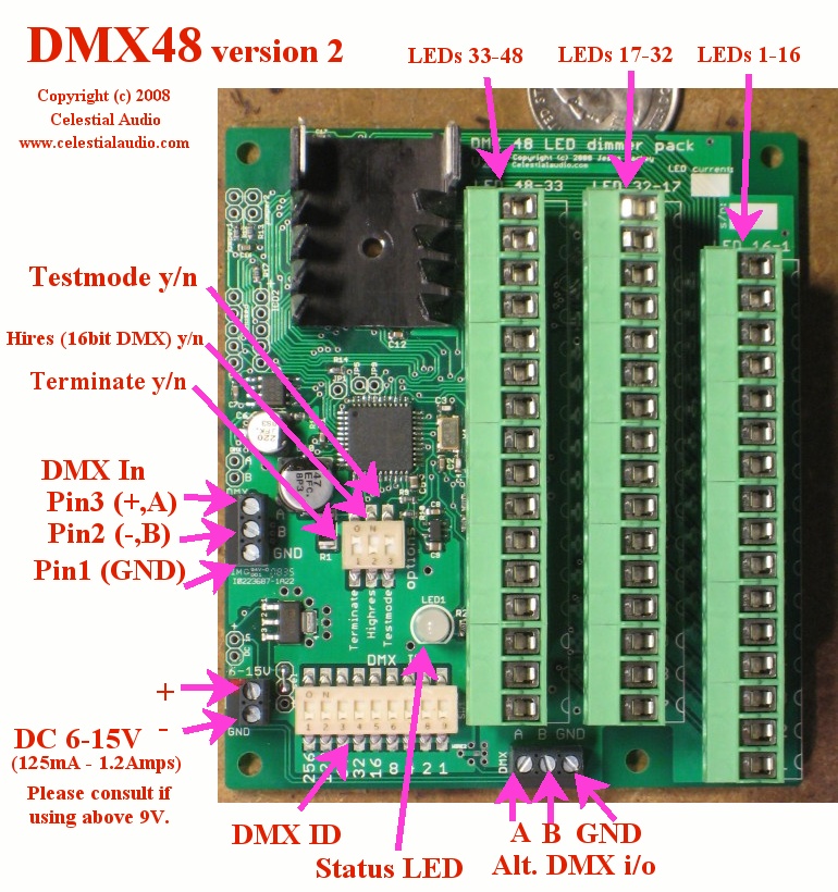
Top view:
Feature set of new Version 2:
- 48 channels with one small board! No more
compromises due to not having as many channels as you really
want.
- Each channel provides 20mA
(can be adjusted for 10 to 80mA - just ask) of
current-controlled switching. No external current limiting
resistors needed. Hook up your LED(s) and go.
- Each channel can switch up to 15V, so several LEDs can be wired in series per
channel.
- 4096 levels of dimming
at a pulse-width-modulation (PWM) refresh rate of 1200Hz. This allows smooth
fade up & down from black with no flicker ever!
- LED brightness levels retained if DMX signal is lost.
- DMX ID settable 1-511 via DIP switch, changes are immediate,
status LED blinks orange to acknowledge setting change.
This is the starting DMX channel the board responds to; for
example, if the ID is 1, the board responds to DMX channels 1
through 49. If the ID is 49, the board responds to DMX
channels 49 through 97.
- DMX termination on/off via DIP switch. No jumpers or
plugs to deal with.
- Test pattern via DIPswitch: fade up all channels to 100%, then
chase all channels, then repeat. Very handy for debugging
installations.
- High-resolution (16-bit DMX) mode yes/no via DIP switch.
- Multicolor status LED indicates DMX protocol or wiring error
(red), no DMX wire connection or no data on connection (green
slow blink), and valid DMX frames incoming (green fast blink).
- Supports the top speed possible with DMX: 512 channel frames @
44fps.
- LED connection headers are a unique "pluggable" design: they
can be unplugged from the board, wires added/removed, then
plugged back in. They can be plugged in two ways: such
that the wires exit up out of the board (shown in in picture) or
more conventionally parallel to the board. This allows for
much easier installation and for moving installations, since the
board and the LEDs are easily separated.
- Board electronics runs from 6-15V DC @ 125mA with LEDs off and
1200mA all-on, reverse polarity protected. Contact me if
75% or more LEDs will be full on for more than 30 seconds at a
time and you are using more than 9V, as there are thermal
concerns. A regulated power supply is suggested; cheap
"wall-wart" supplies typically output several volts higher than their
specification, so a garden-variety "12V" wall-wart may put out
15V or more. This may damage the board. Feel free to
ask me about suitable power supplies or how to tell if yours
will work safely.
- The DMX and DC power input have plated input holes on the
board (in addition to the terminal blocks) to allow wires to be
directly soldered to the board if desired.
- 11 of these boards can be run from a single DMX source, so a
complete DMX universe of 512 channels can be easily built.
- For operating Solid-State Relays, please inquire.
digikey.com 365-1484-ND and 425-2402-5-ND are examples of SSRs
that can be directly switched.
(For existing customers looking for Version 1 information, go here).
Since this board is intended to be installed in an enclosure with
other equipment, and wiring requirements are highly dependent on the
installation, there is no case provided and the DMX connection is
with a terminal block instead of a bulky 3 or 5-pin XLR. See
wiring diagram below for details.
The basic operation is that this board switches the negative of your LEDs to the
power supply's ground. This is called low-side switching, and
is the most common way things like this are done, since it is
simpler, cheaper, and a little more efficient than switching the
positive of the LEDs (called high-side switching).
The wiring diagram is here.
Operation and testing:
- Turn off the LED power supply, and set the board DIPswitches
to: Hires OFF, Testmode OFF, Terminate OFF. Connect the
power supply to the board.
- Turn on the LED power supply. You should see the status LED blinking green slowly.
If not, check that at least 6V is present on the (+) relative to
the (-).
- Turn off the LED power supply, and wire a LED: the LED anode
goes to the power supply, and the LED cathode goes to the board,
use channel 1.
- Turn on the LED power supply. The status LED should
blink slow green. Now turn the Testmode to ON. Your LED should fade up to 100%,
then flash and go dark for a few seconds, and then repeat.
The status LED blinks red/green rapidly. If your LED does
not light, check the wiring and the LED polarity.
- At this time, you're ready to
wire! I don't have a good solution for how to
combine all the LED anodes (+) together; you can use multiple
wire-nuts, or get a multi-position terminal block and wire all
its pins together, or strip 8" of wire and solder the LED anodes
(+) to it. I've done it all these ways and others.
If you've got something handy, please let me know.
- I suggest wiring a half dozen or so channels and verifying
operation with the "Testmode" DIPswitch at this time.
- On to DMX: set the "Testmode" DIPswitch to OFF, choose the DMX
start ID (suggest 1) and set the 9-position DIPswitch for it
(for help with decimal to binary go here),
and
connect
the
DMX
cable
to
the board. If you have a 3-pin or 5-pin DMX cable, you can
cut the end and screw the three wires into the terminal block or
use a 3 or 5 pin to wire pigtails adapter - I normally have a
few for $15. Either of the two DMX terminal blocks can be
used, there are two for wiring convenience for multi-board
installations.
- Flip the "Terminate" switch to ON, and plug into your DMX
source and turn it on. The board status LED should be
flashing fast green. If it is red (meaning garbled data):
the pin 2 / pin 3 is likely backwards or something is
loose. If it is slow green: no DMX is seen; double check
the wiring, that pin 2 / pin 3 / GND is correct, and that your
DMX source is outputting data.
- Now for the fun part:
if the DMX start ID is 1, and your DMX source is outputting data
for channel 1-48, you should be able to fade up and down your
installed LEDs. If there is a lot of flicker, check the
DMX wiring; if one wire is loose there will be lots of bad
data. If the fade up/down looks choppy, compare it with
the fade up the Testmode does. Some lighting control desks
and software don't do smooth ramps; the fade up the Testmode
does shows the board's best capabilities.
Other notes:
- DMX requires that the last (and only the last) DMX device in a
network be terminated; please look elsewhere for more details
about this. The "Terminate" DIPswitch accomplishes this.
- The "Hires" DIPswitch is normally OFF. For finest
dimming control possible (such as from a computer) this can be
turned ON, and the board combines two DMX channels (8bits &
8bits) to create one 16-bit dimming channel so you can set the
brightness to 4096 different levels.
Price: $189
Discontinued March 2011.
To my existing customers: thank you! I will provide consulting
& repairs as needed for the years to come. If you need one
or two more for some reason, please inquire.
To potential new customers: unfortunately I am unable to
produce these at a cost that makes economic sense. If you have
a large-scale project that these or a variation of the design would
work for (i.e. qty 25 or more), please contact me.
DMX LED Home
Celestial Audio Home