DMX controlled 144 RGB LED panel
This web page documents a board with 144 RGB LEDs.
Board size: 9.00 x 9.00 two-layer
Project timeframe: January 2007
Client: Leo Villareal
Webpage created: May 25 2007
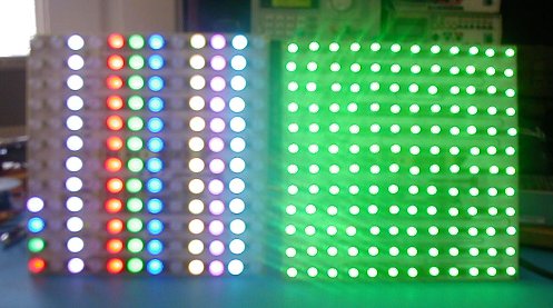
Front - two prototype versions, one with 10mm LEDs (left) and the other
with 5mm (which happen to be showing just green at this instant).
My apologies for the lousy photo:
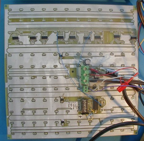
Bottom view:
A great picture of the (beautiful!) final form is here.
(nothing
like pro photography to make my pics look like they were done
by a monkey)
144RGB is something I've wanted
to create for a long time - a full-custom RGB LED panel. This
takes 5V (at up to 8A!) and DMX in, has a switchable "gamma correction"
curve to go from 8-bit DMX to 12-bit PWM in a nonlinear way for better
low-level color fidelity and a variety of built-in test sequences.
This design uses nine TI TLC5940 PWM LED driver chips in a 3-way
mux. (chip details here).
Hardware
design done in collaboration with Todd Polenberg; all software
I did with the CCS C compiler.
The design is misleadingly simple-looking. What works fine at a much smaller scale completely falls
apart when multiplied up by 9X. From finding low enough Ron PFETs
for the mux, to
having to break the 9 TI chips into three chains of three for faster
data loading each mux step (the blue patch wires on the board), to
exhaustive routing (by hand, of course) on a 2-sided board
with 5 multi-amp busses with a low I2R drop requirement so it could run
on 5V (note all the very fat "traces" and sets of vias to connect
these through the board), lots had to work right for the finished
product to
perform flawlessly under all conditions. Sorting out what was
software vs. hardware issues (which could be power, the sometimes bad /
leaky LEDs, or the PFETs) was sometimes a big challenge.
A PIC running code written in CCS C handles the DMX receive, buffering,
and dequeuing while managing the PFET switching and loading the three
sets of 3 TI chips in parallel.
Home